Presented by Robin Whittle
See other video’s on Robin’s YouTube channel:
https://www.youtube.com/channel/UCheSBjUYSDSPebjNnOWKAlA/videos
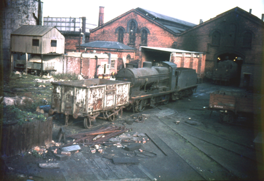
Barrow Road engine shed, the former Midland Railway Roundhouse in Bristol, has always had a particular appeal to me. After research, collecting photographs, maps and other information, I finally plucked up the courage to embark on a project to build a model of the shed and its facilities in 2008.
My first idea was to model the yard between Barrow Road arches and the front of the engine shed. This would have been around 8ft long and have the shed front as the scenic break for the fiddle yard inside the shed building.
I received a lot of input and advice from members of the Scalefour Society Glevum Group and eventually I was persuaded to enlarge the model to include all the roundhouse, the workshop and the yard either side of Barrow Road including the coal and ash plants.
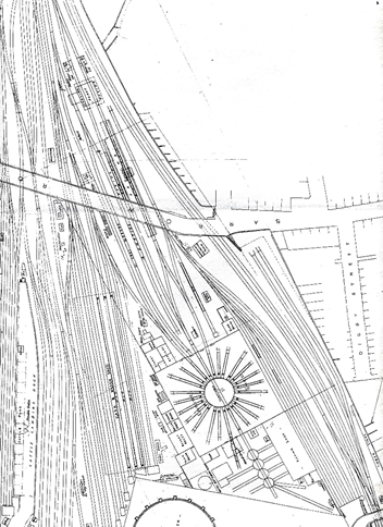
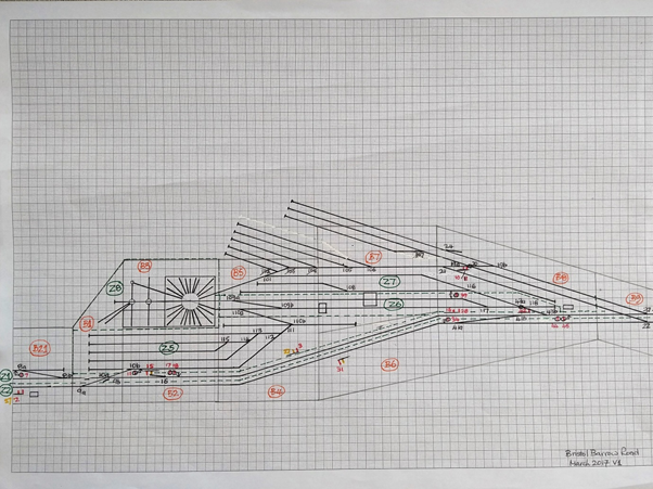
OPC plan of the shed and surroundings. The track around the coal and ash plants does not fit photographic evidence and the model has been adjusted accordingly.
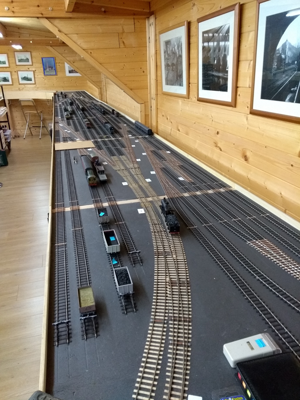
With a modicum of compression in the latter area, the final plan fits on seven boards each 4ft 2in long. This may seem an odd length but only one turnout crosses a board joint. The shed building fits on a board 2ft 2in wide whilst the adjacent sidings and the main line fit on another board 1ft 6in wide, giving a combined depth of 3ft 8in. The total length of the initial scenic section is 16ft 4in. The construction of the boards is such that they can be taken apart and transported to an exhibition if required. Barrow Road has attended a number of society events since 2010 where some or all of these boards have been presented.
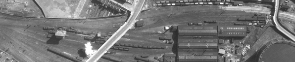
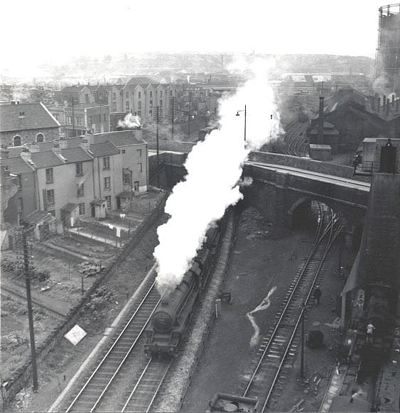
The above photo is a cropped aerial photo from 1948 showing the footprint of the layout.
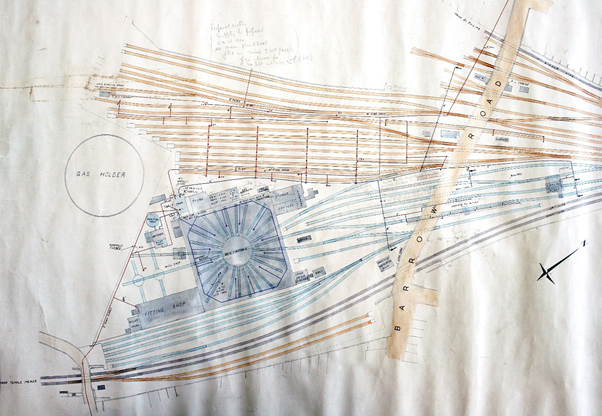
The blue track together with the black double track main line forms the basis of the scenic part of the layout.
Bristol Barrow Road has reached the state where I now have an operational twin track main line passing an operational shed yard. How this happened is the subject of this article.
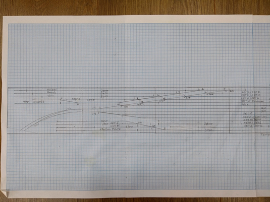
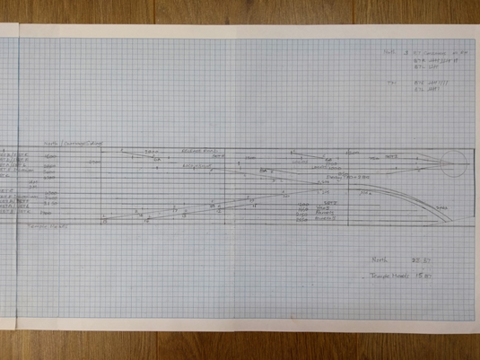
Back in 2009 the embryonic layout was intended as an end to end layout with the main operational focus being the shed yard and roundhouse. At this point all eight baseboards had been constructed, I had started construction of the shed roundhouse and workshop complex and was in possession of a Templot plan of the track work based on an OPC diagram and rating plans.
Forward to the present day and all the track work on the original seven boards has been laid and wired up for DCC operation.
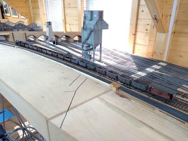
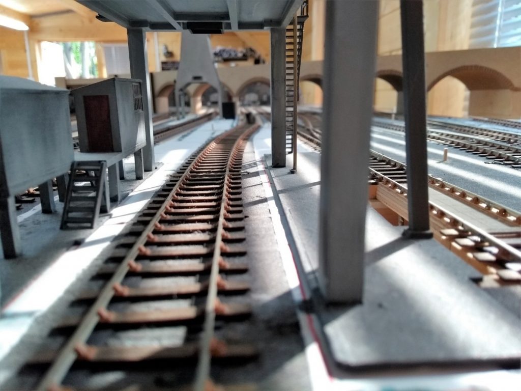
The track has all been hand built using ply and rivet construction together with functional Exactoscale chairs on the scenic sections. On straight track my rule of thumb has been to use rivets on every sixth sleeper with functional chairs on the rest. Straight track is constructed using a jig which takes two 60ft lengths of track and was given to me be my late friend Graham Turner. You will note in the above photograph I lay my track on 6mm wide strips of 0.3mm black card. This tip from Graham enables lifting and removal of sections of track when necessary and is achieved by inserting a palette knife under the card to undo the pva glue. Part of the main line alongside the shed required re-alignment during conversion of the layout into a circuit and being able to lift the track without serious damage was a godsend. I have availed myself of this technique on a number of occasions during the track build including lifting a double slip which leads into the shed yard. I use a variety of track gauges for assembly and have found the Roger Sanders ‘Mint’ gauge particularly useful when constructing turnouts. The other indispensable gauge is the’ Block gauge with crossing alignment aid’ produced by DD Wheelwrights which is used for setting wing rails.
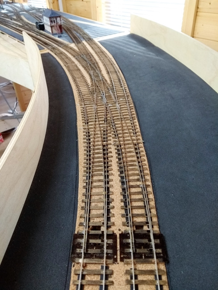
When constructing the track on the new curved boards I used all ply sleeper and rivet construction in order to minimize any problem with gauge. I have used the ‘Mint’ gauge to check for any tightness on the curves and any issues can be resolved by adjustment using the soldering iron.
I originally laid sections of the main line on the first two boards of the scenic section using flexitrack but removed it solely because to me it didn’t look right. However I am using it on the straight sections in the storage sidings.
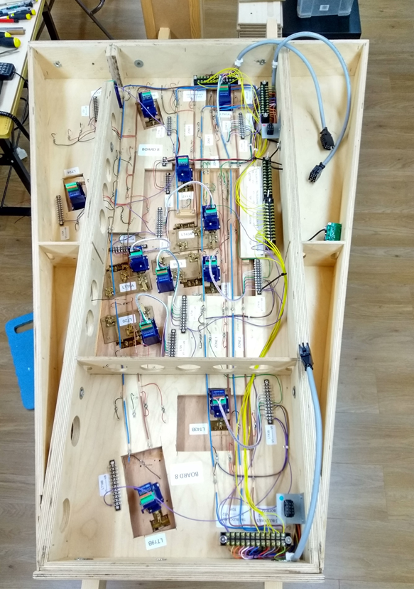
All turnouts have been constructed on the work bench using separate Templot templates. Turnout operation uses Brian Morgan TOUs which are driven by Cobalt motors. At present the yard is operated by digital units whereas the main line will use the analogue version. The reason for this I will come to later. All turnouts have been assigned a number and the scenic section has been divided into eight zones six for the track and two for accessories. Each zone is wired via a PSX1 circuit breaker.
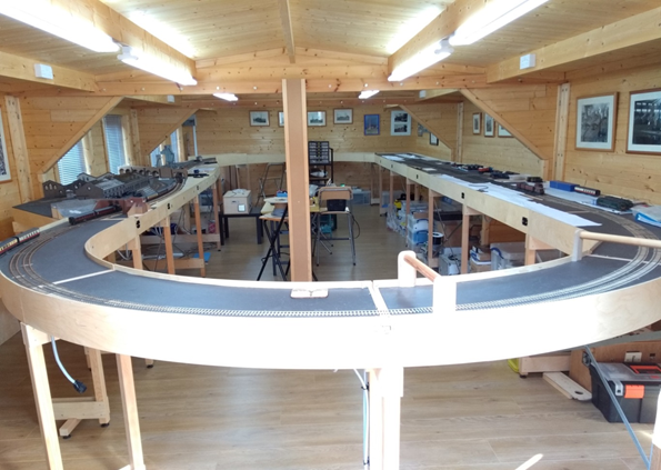
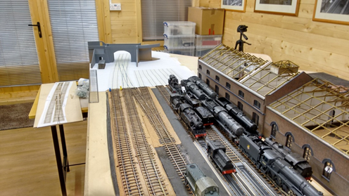
In December 2014, following retirement earlier that year a move of house enabled me to install the layout in a new ‘log cabin’ with outside dimensions of 10m by 5m. With the completion of the new home for the layout I made the decision to enlarge the layout into a complete circuit consisting of an Up and Down main line passing the shed complex and running through a large set of storage sidings.
As there are now 21 baseboards I have decided the layout will remain in its’s new home and will not be available for exhibitions. However, I have invited guests to visit and regular Glevum Group meeting have taken place at the Engine Shed.
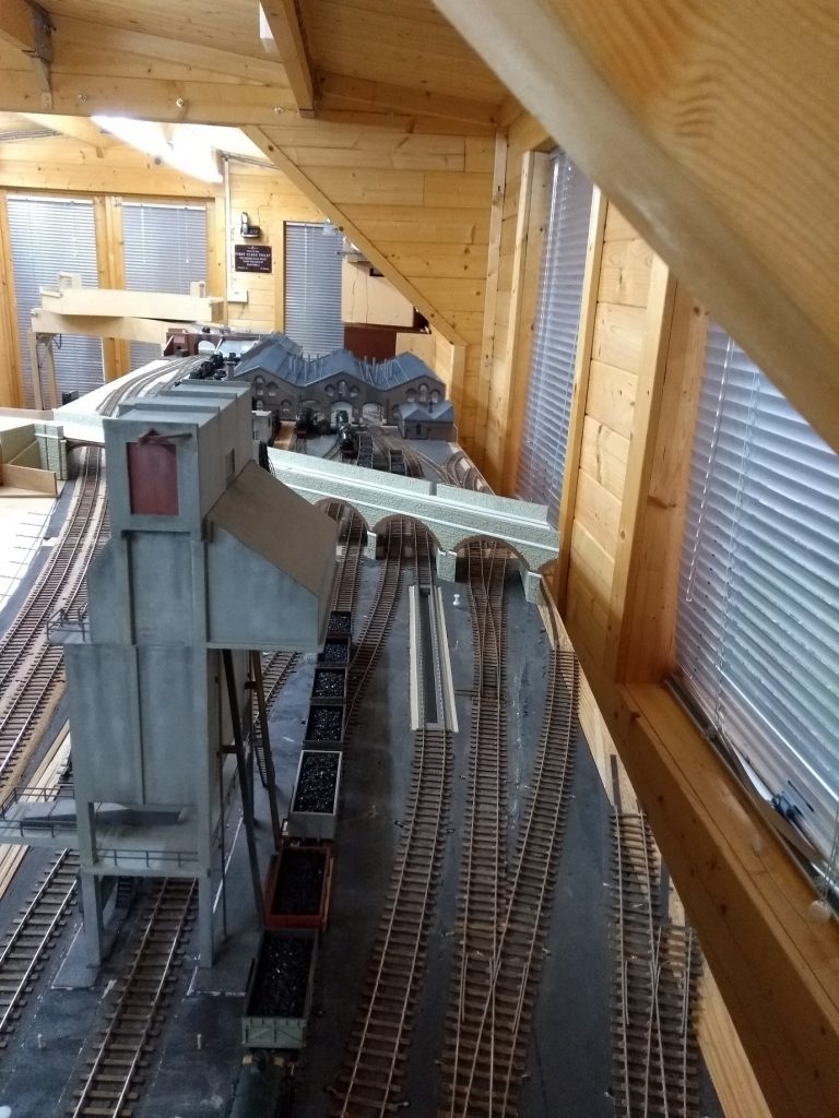
The Engine Shed
The main line past the shed is level until it reaches Barrow Road itself – the arches which bisect the shed yard – and then it rises on a gradient. The prototype is at 1 in 89 but I have reduced this so that the height difference at the summit of the layout is 20mm; a gradient of around 1 in 150.
Planning and build of the new boards was done by my good friend Chris Yates. The minimum curves on the layout are 1400mm, or 4ft 6in in old money, and Chris built an extra 14 baseboards in addition to the original 8. In addition to the challenge of constructing the curved boards at either end of the layout he had to incorporate the change in gradient. The storage sidings are now 10mm higher than the base level of the scenic boards so that from the top of the gradient – Lawrence Hill Junction – to the storage sidings the height drops 10mm whilst from the storage sidings to Days Road Bridge it drops a further 10mm. The change in gradient on a curve has proved a challenge not only in the build but for train operation as well!
Planning the storage sidings required some idea of what trains and stock would be needed and to this end I spent some time working through a number of working timetables for 1958-59 and 1960-1961 this being my preferred period of operation. The end result is the following timetable.
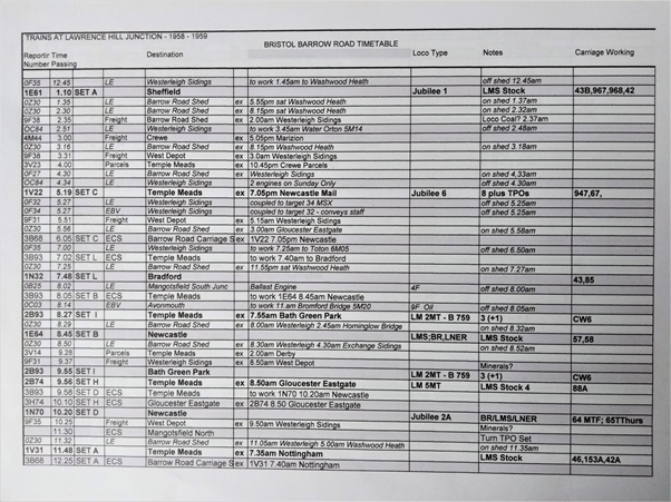
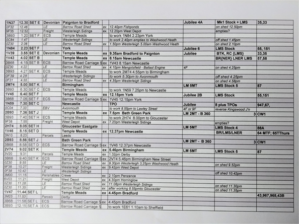
Eleven sets of coaches are required to operate a suitable timetable and their formation was established from a number of sources but principally ‘Operation Midland’ published by Xpress Publishing. A number of trip freights pass the shed and provision for these has been made in the storage sidings.
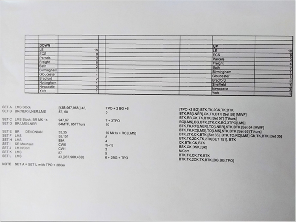
The UP sidings are designated for trains to and from the north of Bristol principally Gloucester, Birmingham, Derby, Sheffield, Leeds and Newcastle. They also serve as Lawrence Hill Carriage Sidings. The DOWN sidings are essentially Bristol Temple Meads. The layout will operate from the Up storage sidings to the Down storage sidings and vici-versa rather than a continuous run although this facility is available to just run trains.
The new storage sidings have four addition zones and circuit breakers two for the track – Up main and sidings; Down Main and sidings, with two for accessories.
Wiring the layout has taken a considerable part of my modelling time over the past year and would not have been achieved had it not been for Chris Yates who produced a full set of wiring schedules for each of the 22 boards.
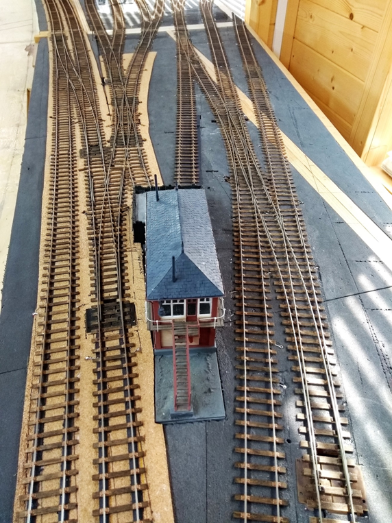
The intention is to have two functional signal boxes controlling the main line as per the prototype. Lawrence Hill Junction controls the double junction to St.Philips at the north end of the layout whilst Engine Shed Sidings controls the south exit from the shed yard and the siding for the banker. These two boxes will be operated using the analogue Cobalt units via a lever frame.
Following completion of the main line circuit a period of line testing was carried out. Various train formations were tested and a number of faults with the track found and rectified. Track levels needed adjustment in places, track on some board end joints needed to be re-soldered and the track gauge needed tweaking at various places. One particular problem area was the double crossing at Lawrence Hill Junction. When testing the front bogie of a number of locos kept derailing. After much scratching of heads Morgan provided a solution to the problem by using the camera slow motion facility on his phone which, on playback, identified the problem as a section of track at the top of the gradient. It so happened that the gradient peaked at the crossing V on the Up main at the double junction. Once identified the summit of the gradient was moved beyond the crossing V and the track given a slight cant with a lengthened wing rail fitted to the crossing. Problem solved.
Progress on the shed buildings and bridges has continued over the intervening years but is nowhere near complete.
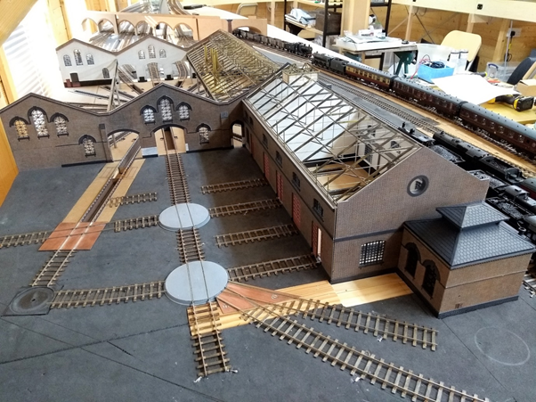
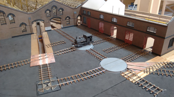
The roundhouse has a new roof constructed from a variety of brass sections using jigs. I reasoned the shed roof would need to be removed to access the interior of the roundhouse and workshop and therefore would need to be robust. The roundhouse roof consists of three removable pitches each being formed by 22 roof trusses. The workshop has twelve. Most of the smoke hoods are cast resin – produced for me by Morgan Gilbert – whilst three are fabricated in plasticard to represent the old wooden version. All have brass tube used for the chimneys.
There are 24 roads radiating around the turntable pit which is CNC machined from an off cut of ‘Corian’ a material used for kitchen work surfaces. The turntable itself is pending with a test etch from London Road Models on my work bench. I managed to obtain a set of works drawings for the actual turntable, a 60ft Cowans Sheldon unit, from Carlisle Records Office.
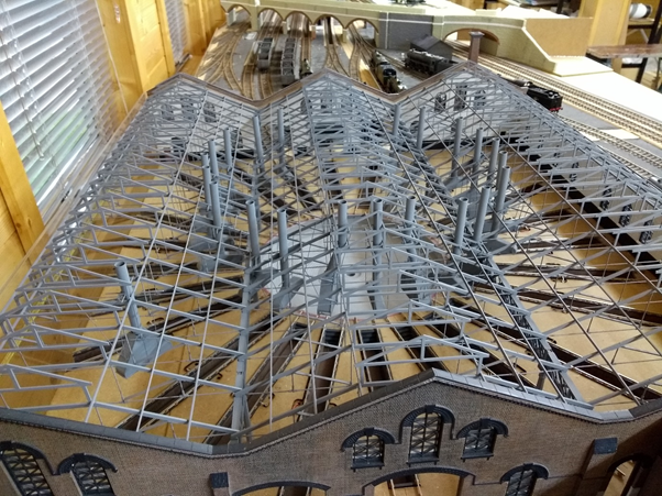
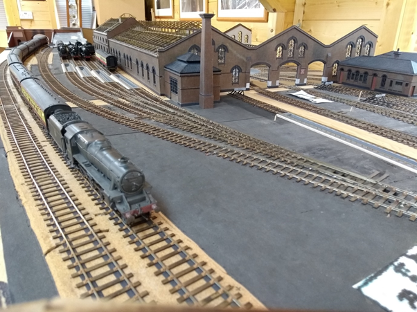
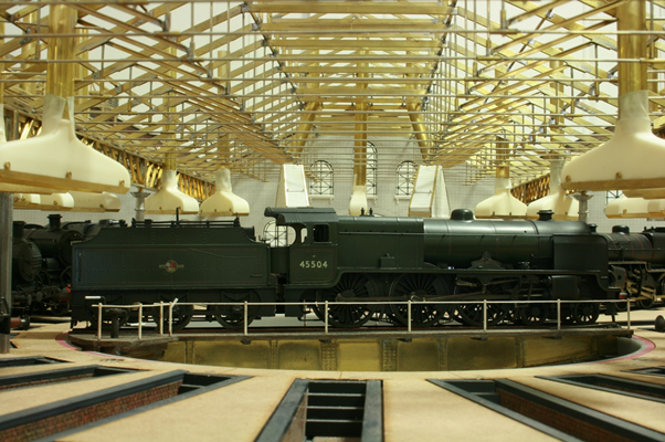
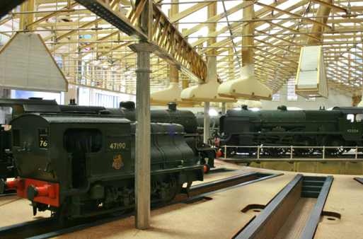
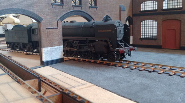
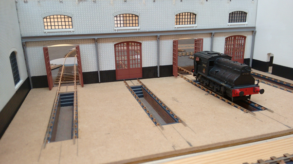
The following photo shows the interior of the shed with Patriot 45504 ‘Royal Signals’ on a turntable borrowed from ‘Brinkley’. These photos show the shed roof prior to the laying of track on the turntable pits.
At the rear of the shed road 15 leads out to the four -road Workshop. Two of the 20ft turntables – they are for locomotives not wagons – remain out of the four originals of the prototype. These are 3D printed and were commissioned from PDH models. They are designed to take a motor and have sprung plunger pickups. Road 14, which as an extended inspection pit, gives access to the hydraulic wheel drop which will eventually have covered building.
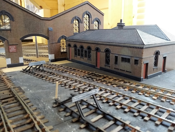
Against the rear wall of the workshop is the boiler house which is the latest building completed. This is made from the same laser etched mdf and Romark plastic as the roundhouse and workshop. All the shed buildings were provided in kit form by York Modelmaking nine years ago and only the small stores building remains to be built. This will be positioned against the wall of the roof pitch to the left of the roundhouse.
Part of the main line past the shed, which included the south exit single slip and crossover, needed to be re-aligned to introduce a more prototypical curve to the track as it passes under Days Road Bridge and sweeps into the curve to the storage sidings.
Whilst rebuilding this track work I commissioned a model of Days Road Bridge from Chris Dening of CD3D Modelmaking. Chris has previously worked for York Modelmaking. The model arrived in grey primer and forms part of the scenic break at one end of the layout.
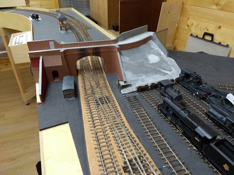
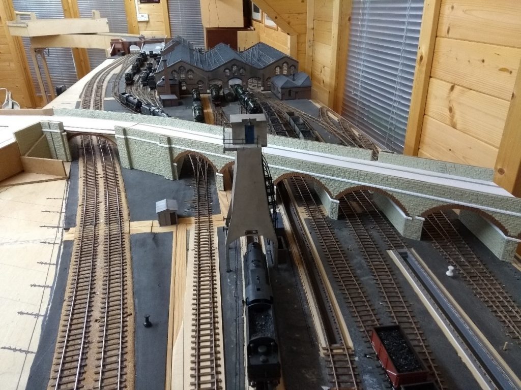
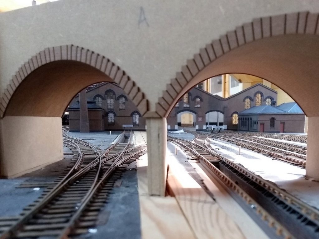
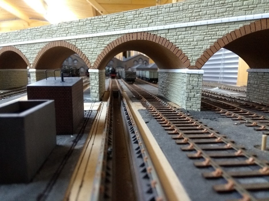
Following the success of Days Road Bridge I asked Chris Dening to produce a model of the basic structure of Barrow Road Arches. As this structure is constructed of Pennant sandstone I asked for the model to include just the arch keystones and the under-arch bricks. The Arches are in the process of adding Wills coarse stone sheet which will be weathered. Thanks to Karl Crowther’s article in MRJ 247.
I would like to thank Chris Yates for his invaluable help with the baseboards, the electrics and assistance with building the ‘Log Cabin. Morgan Gilbert for the original Templot drawings and help particularly with locomotives, rolling stock and the smoke hoods, and all my friends in the Scalefour Glevum Group who have provided assistance and encouragement in this project and no I will not be modelling the two gasometers at the back of the roundhouse.
For those interested in the development of Bristol Barrow Road I have a blog on RMweb and post on the Scalefour Society forum. Both contain videos of trains running on the layout via Youtube links. Articles in MRJ 200, 201 and 209 in which I described the genesis of the layout, Have a look P4 on large layouts does work.